The Influence of Modified Basalt Fiber on the Mechanical Properties of Oil Well Cement (Part 2)
1.3 Characterization and Performance Testing
(1). Characterization of Basalt Fibers
Firstly, use an infrared spectrometer (FT-IR) to analyze the composition of the samples before and after modification of basalt fibers, with a scanning range of 4000-400 cm-1.In order to study the grafting of modified basalt fiber surface coatings, the surface morphology and roughness of basalt fibers were observed using scanning electron microscopy (SEM) at a voltage of 15.00kV, and the proportion of surface elements of basalt fibers was analyzed using energy dispersive X-ray spectroscopy (EDS) under SEM.Subsequently, the fibers were flattened under tension using a fixture, and the hydrophilicity of BF and MBF was measured using an optical contact angle measuring instrument.Finally, the surface Zeta potentials of BF and MBF were measured using a solid Zeta surface potential analyzer with an electrolyte solution of 1 mmol/L KCl.
(2). Dispersion Testing of Basalt Fibers
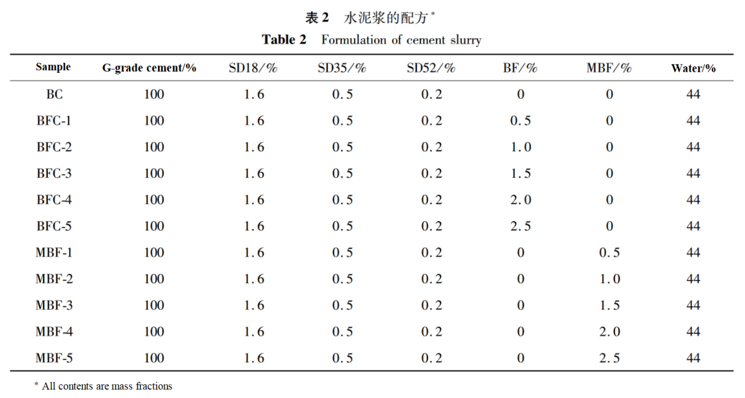
Prepare blank cement slurry (BC), basalt fiber cement slurry (BFC), and modified basalt fiber cement slurry (MBFC) according to GB/T19139-2012 Oil Well Cement Test Method. The specific formulas are shown in Table 2.Pour the cement slurry into the mold for curing and solidification. After curing at 80℃ for 24 hours, the sample was demolded to obtain cement paste, which was then placed in an 80℃ constant temperature water bath for further curing for 2 days.
In order to characterize the distribution of fibers in oil well cement stone, 50.8mm×50.8mm×50.8mm cement stone cores were selected for drilling and cutting. Take 9 samples from each group and observe the surface with a scanning electron microscope, with an observation area of 20mm×20mm.Then use the image processing software Image Pro Plus to binarize the image. During the sample preparation process, the observation surface should be kept as flat as possible, and the maximum height difference should not exceed 1 mm.The processed image has a color difference of 50º or more for brightness and chromaticity differentiation, which can clearly identify the matrix and fibers. Use the fiber distribution coefficient β to evaluate fiber dispersibility.β can characterize the degree of difference in fiber spacing and fiber number in different regions of the same cross-section, and its numerical value can measure the distribution of fibers in cement. The closer the distribution coefficient is to 1, the better the fiber dispersion.
(3). Mechanical Performance Testing of Cement Stone
According to the GB/T19139-2012 standard, the compressive strength and flexural strength of cement stone samples are tested. Use a pressure testing machine to test the compressive strength of cement stone samples (50.8mm×50.8mm×50.8mm).Use an electric flexural testing machine to test the flexural strength of cement stone samples (40mm×40mm×160mm). Then, the microstructure of MBF in cement paste was observed by scanning electron microscopy.
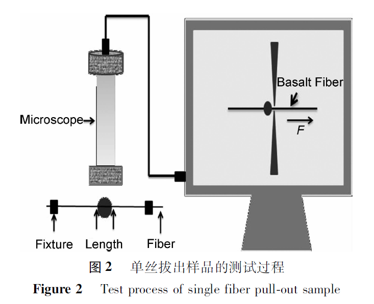
In order to study the interfacial bonding performance between MBF and oil well cement matrix, a single wire pull-out test was conducted, as shown in Figure 2.Place a single basalt fiber in the center of a special mold, drip cement slurry, cure in an 80℃ water bath for 2 days, and demold to obtain a sample of cement wrapped single fiber.Apply a load to the fibers, pull them out of the cement, measure the debonding load F, and calculate the fiber interface bonding strength based on the maximum load of basalt fiber debonding and the depth of fiber embedding in the cement matrix.
2. Results and Discussion
2.1 Structural Characterization Analysis of Basalt Fibers
(1). Infrared Spectroscopy Analysis
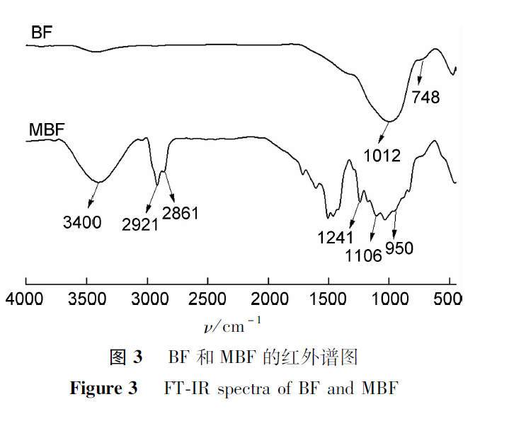
The results of FT-IR comparative analysis of BF and MBF are shown in Figure 3. BF exhibits absorption peaks of asymmetric and symmetric stretching vibrations of Si-O-Si at 1012 cm-1 and 748 cm-1, respectively.However, MBF not only exhibits absorption peaks of Si-O-Si in basalt fibers, but also characteristic absorption peaks of hydrophilic cationic coating agents. The absorption peaks near 2921cm-1 and 2856cm-1 are the stretching vibration peaks of -CH2-, while the absorption peaks near 1241cm-1 and 1106cm-1 are the stretching vibration absorption peaks of C-N and C-O; The peak detected at 950cm-1 is from N+(CH3) 3 of CTAC.In addition, the absorption peak detected near 3400cm-1 may be the hydroxyl group activated during the modification process. The results indicate that hydrophilic cationic coating agents have successfully coated the surface of modified basalt fibers.
(2). SEM and EDS Analysis
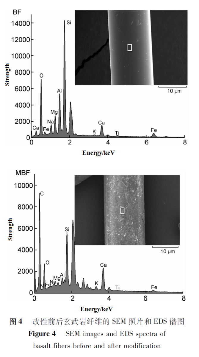
Figure 4 shows SEM images and corresponding EDS analysis results of BF and MBF. It can be seen that the surface of BF is smooth, while the surface of MBF is rough and has obvious material coverage.According to EDS analysis, BF is mainly composed of O, Al, Si, and small amounts of other metal oxides such as Na, Mg, K, Ca, Fe, etc.Compared with BF, the elements detected in MBF samples are basically the same, but MBF still contains a large amount of carbon elements, and nitrogen elements were also detected, all due to the introduction of hydrophilic cationic coating agents on the surface of MBF. Therefore, it can be inferred from the above analysis that the modification of basalt fibers has been successful.
(3). Contact Angle Analysis
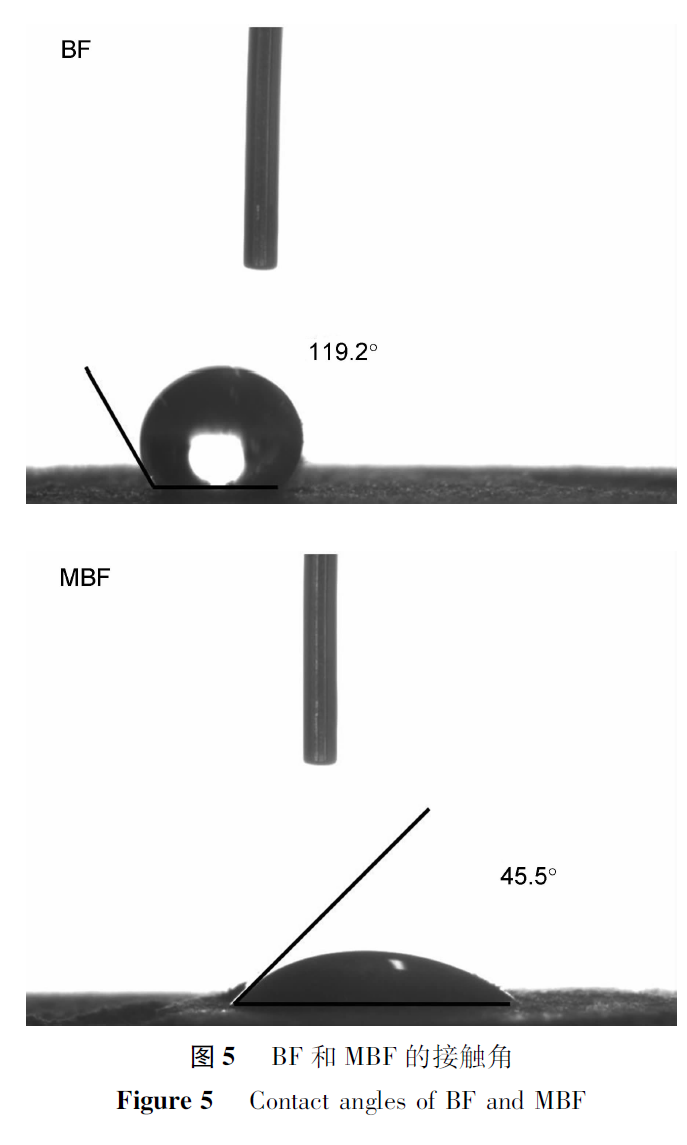
Figure 5 shows the static contact angles of BF and MBF. According to Figure 5, the contact angle of BF is 114.8º, indicating a hydrophobic state. This is because the surface of basalt fibers is smooth and inert, without polar hydrophilic groups such as hydroxyl, carboxyl, and amino groups, resulting in poor hydrophilicity.The contact angle of MBF is 45.1º, which is smaller compared to BF. This is because the introduction of carboxyl and quaternary ammonium groups significantly improves the hydrophilicity of BF.
(4). Zeta Potential Analysis
The Zeta potential measurements of hydrophilic cationic coating agents, BF, and MBF are shown in Table 3. The hydrophilic cationic coating agent exhibits a positive charge with a Zeta potential of +32.47mV, which is due to the introduction of cationic N+(CH3) 3 groups in the hydrophilic cationic coating agent.The BF surface exhibits electronegativity with a Zeta potential of -9.32mV, The surface Zeta potential of MBF is +22.30mV, indicating the successful introduction of N+(CH3) 3 groups onto the MBF surface.The increase in Zeta potential, due to electrostatic repulsion, can enhance the dispersibility of MBF in water-based environments. At the same time, the surface of cement particles exhibits electronegativity, and positively charged MBF can better bond with the cement matrix.

