Performance Evaluation of Cement Sheath in Jimusaer Shale Oil Well(Part 1)
Abstract
Hydraulic fracturing technology is an important means to improve the production capacity of shale oil wells, and the mechanical behavior of well cementing cement during the fracturing process has a significant impact on the safety and efficient production of oil and gas wells. Based on the formula of the cementing slurry system in the Jimusar area, a cement sample curing mold and a cement bonding strength testing plan were designed. Standard cylindrical cement stone samples and cement stone bonding samples were cured, and single/triaxial compression experiments, cyclic loading experiments, and bonding strength experiments were conducted under simulated wellbore conditions to explore the damage and failure laws of the cement stone body and bonding surface. The research results show that under uniaxial compression conditions, cement paste has significant elastic and brittle characteristics. When the cement body is damaged, macroscopic cracks form, and the average elastic modulus of cement is 3.054 GPa, and the average Poisson's ratio is 0.127; Under triaxial conditions, the strength and plasticity characteristics of cement stone are enhanced; During the cyclic loading process, there is a bilinear accumulation phenomenon in the plastic deformation of cement stone. The amount of plastic deformation is positively correlated with the peak load. When the peak load increases from 22.7 MPa to 53.2 MPa, the plastic strain after 20 cycles increases from 0.24% to 2.46%; The cement bonding surface is a natural mechanical weak layer, and the cement stone bonding strength is less than 1 MPa, far lower than the strength of the cement stone body, which is the risk point for wellbore sealing failure.
The efficient development of shale oil is of great significance for alleviating the energy supply and demand gap in China. Domestic oil fields such as Xinjiang, Changqing, Daqing, and Dagang have all commercially developed shale oil. From 2020 to 2022, the annual production of shale oil in Jimusaer, Xinjiang Oilfield was 32.2×10⁴t, 42.6×10⁴t and 50.9×10⁴ tons,respectively, and has achieved a significant leap in production, leading the development of terrestrial shale oil in China. Shale oil reservoirs have the characteristics of low porosity and low permeability, requiring the use of horizontal wells and volume fracturing to obtain commercial oil flow. At present, during the fracturing process of the Jimusaer shale oil well, the wellhead pressure limit is 90 MPa, and the fracturing stage is around 35 levels. The cyclic loading and unloading of the internal pressure of the casing during multi-stage fracturing pose a serious challenge to the sealing integrity of the wellbore cement ring. Compared to casing metal alloys with higher elastic modulus and yield strength, cement rings have lower elasticity, toughness, and strength. When the internal pressure of the casing increases, the radial stress borne by the cement sheath increases. When it exceeds the elastic limit, the cement material enters a plastic state. After unloading the internal pressure, due to the significant difference in mechanical parameters between the casing and the cement sheath, the displacement of the two on the bonding surface is not synchronized, and the contact stress on the bonding surface decreases. The multiple loading and unloading of the internal pressure of the casing continuously accumulate the plasticity of the cement material. When the contact tensile stress on the bonding surface exceeds the interfacial tensile strength, a micro annular gap is generated; Secondly, if the radial stress borne by the cement sheath exceeds the compressive strength, the cement sheath will experience compression failure during a single fracturing process.
Micro annulus and compression failure are considered the main forms of cement sheath failure in multi-stage fracturing processes. In terms of analyzing the mechanical properties of cement rings, it is generally believed that the external factors that affect the stress state of cement rings mainly include: internal pressure of the casing, geostress state, wellbore temperature changes, corrosion environment, eccentricity conditions, etc; The internal factors mainly include the elastic modulus of cement sheath, Poisson's ratio, cohesive force, internal friction angle, bonding strength, etc. Under high strength and low stiffness conditions, the cement sheath has a wider range of elastic deformation, and the plastic accumulation of the cement sheath under cyclic loading conditions is also small. However, achieving this performance requirement is difficult. The main reason is that increasing elasticity means adding some elastic materials such as fibers, latex, nanoparticles, etc. to the cementitious slurry to fill the pores between hydrated calcium silicate and increase the overall elastic performance, However, the overall strength of this material is relatively low, which reduces the overall strength of cement.
Based on comprehensive consideration of the fracturing construction parameters and geological conditions of shale gas wells in the Sichuan Basin, Zhao Changqing et al. believe that when the elastic modulus of the cement sheath is less than 7 GPa and the triaxial compressive strength is greater than 40 MPa, its integrity can be ensured during the fracturing process; Xu Xinnin et al. provided fracturing operation parameters and optimal mechanical performance parameters of cement stone to avoid cement sheath failure in horizontal well sections through simulation evaluation; Li Qixuan et al. conducted thermal cycling experiments on cement stone, measured the longitudinal and transverse wave velocities of sound waves propagating in cement stone under different thermal cycling conditions, and analyzed the dynamic mechanical parameter changes based on the relationship between wave velocities and dynamic elastic parameters. From existing research, it can be seen that the evaluation methods for shale oil and gas well cementing cement mainly refer to conventional oil and gas wells, with a focus on compressive, tensile, and flexural strength. However, there are relatively few parametric analyses related to the accumulation of cement sheath plasticity and the generation of micro annular gaps during multi-stage fracturing processes.
This study takes the cement slurry system used in the Jimusaer shale oil well as the experimental object. Based on simulating the maintenance of the underground environment, the performance evaluation and analysis of cement stone are carried out to clarify the mechanical behavior of cement stone during single/triaxial and cyclic loading processes, quantify the bonding strength of the cementing surface, and provide data reference for improving the cementing quality of Jimusaer shale oil wells in Xinjiang Oilfield.
1. Sample Preparation and Experimental Plans
1.1 Sample Preparation
In this study, the cement slurry formula for casing cementing in the Jimusaer area was used. The detailed ratio is: G-grade cement (750 g), solid fluid loss agent QS-14S (18.75 g), anti channeling agent BH-LFM (15 g), anti channeling agent FLOK-2 (30 g), elastoplastic agent ELP-1S (1.25 g), and fresh water (350 g).
Referring to the national standard for oil well cement (GB/T 10238-2015), pour the evenly mixed cement slurry into a cylindrical mold (internal dimensions Φ25 mm×50 mm, Φ25 mm×15 mm, Φ50 mm×50 mm) for molding is poured into shape, and the Φ25 mm×50 mm mold curing sample is a pure cement sample, corresponding to uniaxial/triaxial testing of cement stone; The Φ25 mm×15 mm and Φ50 mm×50 mm mold curing samples are cement bonding samples, corresponding to the normal bonding strength and tangential bonding strength experiments of cement. After the maintenance is completed, the demolding, cutting, and section grinding processes should be carried out. It should be ensured that the non parallelism of the specimen end face is less than 0.05 mm, the radius error is less than 0.3 mm, and the deviation of the end face perpendicular to the axis of the specimen is less than 0.25 °, in order to obtain a standard rock core that meets the experimental requirements and specifications.
1.2 Experimental Plans
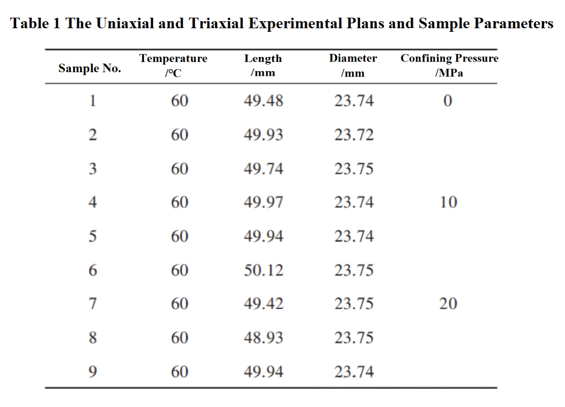
Considering that this study requires conducting 5 different types of experiments, single and three-axis experiments and cyclic loading experiments are mainly conducted directly using the hydraulic servo experimental testing system (TAR-155) produced by Changchun Huiyang Company. Three sets of uniaxial experiments, six sets of triaxial experiments, and three sets of cyclic loading experiments were designed to clarify the stress-strain patterns of cement column samples under single loading and cyclic loading conditions at the bottom of the well. The uniaxial and triaxial experimental plans and sample parameters are shown in Table 1.

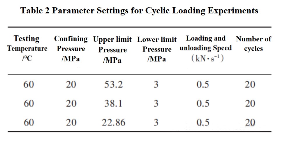
On the basis of clarifying the uniaxial and triaxial compressive strength of cement stone, further loading-unloading experiments were conducted on cement column samples under different cyclic loading peak conditions to analyze the cumulative plastic deformation characteristics of cement columns. The confining pressure is set to 20 MPa to prevent premature breakage of cement during the loading process. In order to quantify the impact of different alternating loads on the plastic accumulation of cement, the peak cyclic load is set to 70%, 50%, and 30% of the peak deviatoric stress, and the valley load is set to 3 MPa. Loading and unloading adopt stress control method, with a rate of 0.5 kN/s and 20 cycles. The specific parameter settings are shown in Table 2.

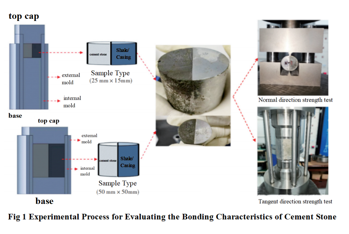
For the testing of bond strength, it is mainly divided into shear bond strength testing and tensile bond strength testing. Considering the limited analysis on bond strength testing, relevant bond strength testing molds have been designed, as shown in Figure 1.

This mold is mainly used to form a bonding surface between the rock core and cement, as well as a bonding surface between the casing and cement. The specific implementation plan is as follows: make the Jimusaer shale oil well core into a standard rock sample, divide it into half cylinders along the top, place it inside the mold, pour cement slurry, and place it in a curing box for curing. Afterwards, it can be used to test the bonding strength between the cement sheath and the formation; For the bonding strength test between the casing and cement stone, the main method is to mill the casing material into a semi-circular column shape, and the subsequent steps are the same as the bonding strength test between the rock core and cement mentioned above.
After maintenance is completed, take out the bonded samples for normal bonding strength testing and tangential bonding strength testing. The normal bonding strength refers to the maximum radial tensile load that the bonding surface can withstand, and its value has a significant impact on the calculation of micro annular gap size in multi-stage fracturing processes. The specific experimental process is as follows: place the cured sample on the experimental bench, ensuring that the straight line formed by the upper and lower pressure heads is parallel to the boundary line of the sample material. After starting the equipment, monitor the displacement and load of the pressure head sensor, and take the peak load to calculate the normal bonding strength, as shown in formula (1).
.png)
Where:
σt —Normal bonding strength,MPa;
Fmax—Peak load of pressure head,kN;
L—Sample thickness,mm;
d—Sample diameter,mm.
Tangential bonding strength refers to the maximum shear load that the bonding surface can withstand. Tangential bonding strength is mainly used to suspend and support the casing, preventing displacement of the casing in the axial direction. The specific testing method is as follows: place the cured sample on the experimental bench, clamp the half cylinder on one side of the rock, and suspend the lower part of the half cylinder on the other side. After starting the equipment, the semi-circular pressure head moves downward to generate shear stress on the bonding surface until the sample is sheared and damaged. Record the displacement and load of the pressure head sensor, and take the peak load to calculate the tangential bonding strength, as shown in formula (2).
.png)
Where:
σs—Tangential bonding strength,MPa.
