Nano Toughened Cement Slurry Cementing Technology for Shale Gas Slim-Hole Horizontal Wells(Part 2)
2.3 Mechanism Analysis
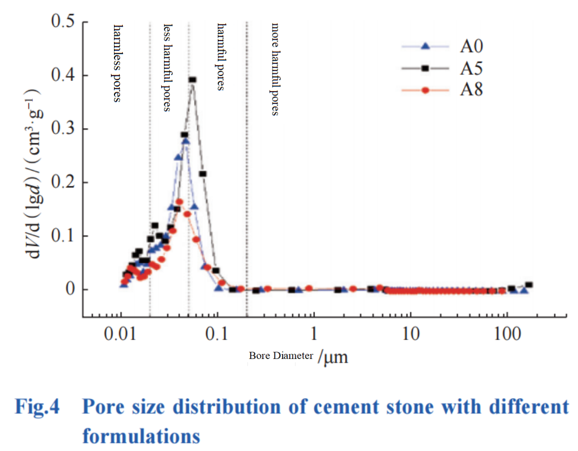
Cement stone is a porous material that contains a large number of pores, which is very detrimental to the improvement of its mechanical properties. Exploring its pore size distribution can explain the internal reasons for its strength improvement from a mechanistic perspective. The pore size distribution of cement paste formulations A0, A5, and A8 were tested separately, and the results are shown in Figure 4 (in Figure 4, the classification standards and methods for harmless pores, less harmful pores, harmful pores, and more harmful pores are referred to in the literature).

As shown in Figure 4, formula A0 cement slurry does not contain fibers and nanotubes, resulting in a wide range of pore size distribution in the formation of cement paste, and even a certain number of harmful pores with pore sizes greater than 100μm. The test results are highly consistent with the design concept of cement slurry. Fiber was added to formula A5 cement slurry. Due to the larger size of the fiber, it increased the number of harmful pores in the cement paste when combined with cement hydration products, and the peak pore size was located in the harmful pore area. The formula A8 cement paste is added with carbon nanotubes, whose own aspect ratio can bridge the gap between the fiber and the cement paste, and the space network structure formed is filled in the gel pores of the hydration products and the nano and micro pores of the cement matrix; At the same time, nanomaterials can to some extent promote the formation of hydration products to further fill capillary and macropores, keeping the peak pore size away from harmful pore areas, and making the cement paste more dense. Therefore, the cement stone with formula A8 not only has zero harmful pores, but also significantly reduces harmful and less harmful pores, which is beneficial for the cement stone to resist damage and prevent the erosion of formation fluids.
2.4 Routine Performance Indoor Evaluation
Prepare cement slurry according to formulas A0 and A8, test their free liquid content, filtration loss, rheological parameters, and thickening time, and compare them. The results are shown in Table 2. According to Table 2, the compatibility between the composite material and additives in formula A8 is good. The free liquid and thickening time of the cement slurry prepared according to formula A8 can meet the construction requirements, and the stability and filtration loss are better than those of the cement slurry prepared according to formula A0. This is mainly because the nano material and fiber material form a multi-scale network structure in the slurry, which can effectively prevent particle settling and quickly form a dense thin filter cake during filtration loss testing, reducing filtration loss. Overall, nano toughened cement slurry can be used for well cementing construction.

2.5 Supporting Mixing Process
The fibers in the nano toughened cement slurry system can be fully mixed with solid phases such as cement at the mixing station. However, carbon nanotubes have a small size and are prone to entanglement, making it difficult to disperse, making it difficult to mix evenly with the ash material in the mixing station. At present, ultrasonic dispersion technology is mainly used indoors to solve this problem, but there is no large-scale ultrasonic dispersion equipment that can achieve continuous mixing on site. Therefore, although there have been many studies on carbon nanotube cement slurry both domestically and internationally, there are no on-site application examples. In response to this issue, a three-stage mixing method was studied and designed, which includes indoor ultrasonic dispersion for producing concentrated liquid, on-site mixing with a liquid truck for secondary dispersion, and cement truck for secondary mixing and slurry preparation. This significantly improved the dispersibility of high-dose carbon nanotubes in the slurry, and for the first time achieved on-site application of carbon nanotubes in well cementing.
3.On Site Testing
YYP-10 well is a shale gas exploration horizontal well in the southeastern part of the Ordos Basin. The horizontal section of the well was drilled with a ϕ152.4mm drill bit, with a complete drilling depth of 3760m, a vertical depth of 2532m, and a horizontal section length of 1010m. A ϕ114.3mm production casing was used for one-time upward cementing technology. Due to the presence of weak strata in the upper part of the area, a dual density cement slurry cementing technology was adopted, which includes low-density cement slurry to seal the upper part and nano toughened cement slurry to seal the lower part. A total of 60m3 low-density cement slurry with a density of 1.35 kg/L and 50m3 nano toughened cement slurry with a density of 1.90 kg/L were injected into the well, ensuring a safe and smooth cementing construction process. The logging results show that the qualification rate of cementing quality in the horizontal section of the well is 98%, and the excellent rate is 86%.
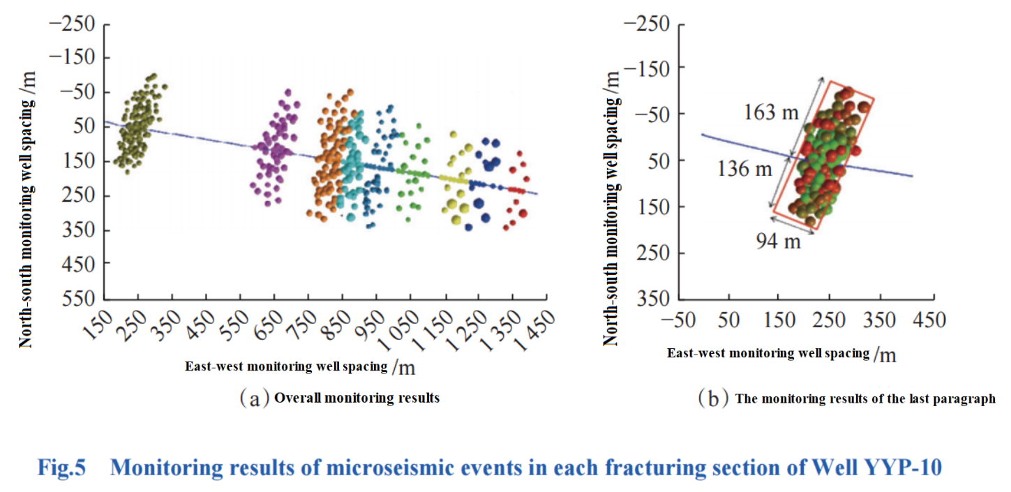
Although domestic and foreign experts have conducted extensive evaluation studies on the integrity and sealing ability of cement rings, there is currently no reference and intuitive method for evaluating the effectiveness of underground sealing. This article uses indirect methods for judgment. Due to the fact that volume fracturing is carried out in stages and sequentially from the toe to the heel, monitoring the extension direction of cracks in the fracturing section and the formation time of various crack networks can qualitatively evaluate the sealing effect of cement rings between segments and clusters. The microseismic monitoring method is used to monitor the fracturing fractures in the well. The monitor is located in the adjacent well near the root of the horizontal section, with a distance of 292 to 1350 meters from each section. The microseismic event positioning error is between 0.50 to 2.90 meters. The horizontal section of the well was fractured in 9 sections, and the microseismic monitoring results of each section are shown in Figure 5 (a). The spherical particles in the figure represent the monitored individual microseismic events (crack distribution), and different colors represent artificial cracks generated at different times and sections. The closer the distance to the monitoring signal well, the stronger the monitoring signal, and the more microseismic events are monitored. Analyzing the distribution of cracks detected in each section, it can be concluded that during the single section renovation, the integrity of the cement sheath outside the casing is good, which hinders the fracturing fluid from flowing along the cement sheath into the renovated section, allowing it to fully enter the corresponding target formation in that section. Micro seismic events perpendicular to the wellbore direction and uniformly distributed between the clusters within the section are generated; There is a clear boundary between each fracturing section, and the occurrence of microseismic events is zero, achieving the goal of segmented transformation.

The crack monitoring results during the fracturing of the 9th section are shown in Figure 5 (b). This section is closest to the monitoring well, so the monitoring error is the smallest. Accordingto Figure 5 (b), it can be seen that the fracturing fractures can be controlled within the designed range of 94 meters along the wellbore axis, with 143 microseismic events. There are 0 microseismic events at the upper and lower ends of the wellbore axis outside the wellbore section, indicating that the cement ring here still has good sealing ability after 8 cycles of loading and unloading, and the formation fracturing transformation effect is good.
4. Conclusions and Recommendations
1). Through the synergistic effect of fibers and carbon nanotubes, the elastic modulus of cement stone can be reduced, its tensile strength can be improved, and a nano toughened cement slurry with low free liquid content and filtration loss, strong stability, and denser density can be developed to meet the cementing needs of shale gas small wellbore horizontal wells.
2). The problem of easy entanglement and difficult dispersion of carbon nanotubes themselves is a bottleneck that restricts their large-scale application in oil and gas well cementing engineering. It is necessary to further develop efficient dispersion technology and supporting processes for high-dose carbon nanotubes in cement slurry, and develop high-performance cement slurry systems using the advantages of the materials themselves is the future development direction of this technology.
3). The use of crack detection technology during fracturing can qualitatively analyze the sealing effect of cement rings, but cannot quantitatively evaluate the sealing ability. It is recommended to further study the quantitative evaluation method of sealing ability.
