Hydraulic Shaping Technology for Deformed Casing after Fracturing in Shale Oil Horizontal Wells
This article conducted technical research on the casing shaping of shale oil horizontal wells, improved and developed a series of shaping tools, combined with indoor test results to improve the construction process, and achieved success in the on-site test of the shale oil horizontal well GD1701H in Cangdong Depression, providing a channel for the next step of continuous pipe plugging and restoring the full well section production capacity.
1. Current Situation of Shale Oil Horizontal Well Casing Transformation
If the casing deformation point is near target A, segmented bridge plugging cannot be implemented during volume fracturing, and the well section that cannot be modified after casing deformation generally gives up construction. When put into production, the wellbore cannot meet the requirements of continuous pipe plugging, resulting in low shale oil production, short development time, and ineffective utilization of well control resources.
In order to reduce the probability of casing deformation caused by volume fracturing, in addition to optimizing the fracturing process, increasing the steel grade and wall thickness of the casing is also used to enhance its deformation resistance. The number of casing deformation in shale oil horizontal wells has been effectively controlled. However, the mechanism of casing damage in shale oil horizontal wells is complex and has multiple influencing factors. There are also many types of casing damage, such as thread leakage, casing body perforation, and casing variable diameter reduction. Among them, the proportion of casing variable diameter reduction is the largest. The first two types of casing damage wells can resume production by using subsidy or expansion pipe processes. The difficulty of casing variable diameter reduction treatment is high, and there are no mature cases in the industry for reference.
2. Conventional Hydraulic Shaping Technology and its Shortcomings
The ball breaks and deforms, falling into the well. The hardness of the ball design is relatively high, and it is easy to break and fall into the well when compressed; At the same time, the ball groove is deformed due to the compression of the ball, causing the ball to squeeze out and fall into the well.
The tool string is subjected to uneven force and broken. The total length of the expansion sleeve tool string reaches 10-15 meters, and the tools are rigidly connected by threaded connections. Under the thrust of the hydraulic cylinder, the expansion head of the pipe expander cannot accurately align the wellbore, and the axial and radial forces on the tool string are uneven, posing a risk of breaking and falling into the well.
The effective period of casing rebound is short. After the maximum outer diameter section of the conical expansion head passes through the deformation point, the deformation sleeve rebounds and gets stuck in the expansion pipe; Even more serious is that after conventional hydraulic shaping and repair, the casing rebounded and returned to its original deformation state in a short period of time, causing the production pipe string to get stuck. Multiple similar cases have occurred on site.
3. Hydraulic Shaping Tool for Shale Oil Horizontal Wells
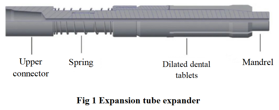
Expansion tube expander. The expansion tube expander, as shown in Figure 1, consists of a core shaft and an expansion tooth piece. The outer side of the core shaft and the inner side of the split expansion tooth piece are designed with a 6°to 8°taper slope.

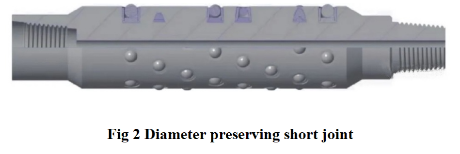
Diameter preserving short joint. The diameter preserving short joint, as shown in Figure 2, is connected to the rear of the expansion tube expander, with the outer diameter consistent with the maximum diameter of the expansion head of the expander.

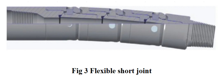
Flexible short joint. The flexible short joint, as shown in Figure 3, is connected by a single thread of a flexible drill pipe. The length of the single thread is 0.15 m, the angle of the movable joint is adjustable from 0°to 4.5°, the rated torque is 25 kN·m, and the tensile strength is 1200 kN.

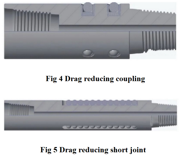
Drag reducing couplings and drag reducing short joints. We have designed drag reducing couplings (see Figure 4) and drag reducing short joints (see Figure 5), which are installed in the tool string and the pipe string at the high inclination section, respectively.

Tool combination. The downhole tool string combination for hydraulic shaping of shale oil horizontal wells from bottom to top is: expansion pipe expander + diameter preserving short joint + (spiral scraper) + flexible short joint + power rod + multi-stage hydraulic booster (booster hydraulic cylinder) + hydraulic anchor group + pressure relief valve+hydraulic anchor group + shaker + accelerator + 18°slope drilling rod.
4. Laboratory Experiment
Test equipment. Experimental platform, ϕ 139.7 mm × 12.7mm TP125V grade casing, press, series casing hydraulic shaping tool.
Test steps. 1) Fix the casing on the test bench, apply pressure with a press, convert the external extrusion force to 870 kN, and deform the inner diameter of the casing from 118.6 mm to 47.0 mm, simulating downhole deformation of the casing. 2) Fix the casing on the test bench, and connect the push rod of the test bench to the expanding pipe expander to simulate the process of repairing the downhole casing.
Experimental results. The indoor test results show that the hydraulic shaping technology for shale oil horizontal well deformed casing is feasible. The downward thrust generated by the hydraulic force continuously expands the diameter of the shaping and expanding pipe, restoring the inner wall of the casing to a circular state, thereby achieving the goal of repairing the deformed casing. The test results also indicate that during construction, it is necessary to consider aligning the expansion head, and the expansion head should be implemented step by step from small to large.
5. Field Test
The hydraulic shaping technology for deformed casing in shale oil horizontal wells has been successfully tested on site in two vertical wells, Zhuang 6-12-10 well and Xi 36-4 well. Afterwards, the technology was tested on-site in the shale oil horizontal well GD1701H.
Through the reasonable configuration and careful construction of the expansion tool, and after repairing 7 times, the diameter of the GD1701H well casing was restored from 94.75 mm to 115.60 mm, with a recovery rate of 97.45%, and the rebound stress of the deformed casing was eliminated.
The ϕ112.0 mm ×1.20 m wellbore gauge smoothly passed through the deformed section to the bottom bridge plug, and successfully swept the ϕ50.8 mm continuous tubing and ϕ79.0 mm×4.90 m screw drilling tool and ϕ108.0 mm grinding shoe to the bottom of the well. After six months, the injection was stopped and the pump was put into operation under pressure. The liquid production increased from 9.6 cubic meters/day before repair to 23.2 cubic meters/day. In the later two pump maintenance and construction inspections, no casing deformation was found, and the casing repair construction effect was good, meeting the needs of geological development.
6. Conclusions and Recommendations
1) We have improved and developed a series of downhole tools, improved on-site construction technology, and formed a series of technologies such as automatic alignment of expansion heads, rolling reinforcement of casings, and auxiliary unblocking.
2) Indoor experiments have shown that high steel grade casing in shale oil wells requires a large shaping force and high tool requirements, making it relatively more suitable to use expansion type pipe expanders. During construction, it is necessary to ensure that the expansion head can be automatically aligned.
3) On site experiments have shown that the hydraulic shaping technology for deformed casing in shale oil horizontal wells can restore the inner diameter of the casing, avoid fracturing loss, and meet the needs of continuous pipe plugging to restore the energy of the bottom well section during production.
4) The hydraulic shaping technology for deformed casing in shale oil horizontal wells should follow the technical concept of "reducing grade difference, combining expansion and rolling, flexible alignment, and shock prevention" to select downhole tools, and make timely adjustments based on the downhole display and the degree of wear of the lifting tool.
5) It is recommended to further establish a theoretical model, accurately calculate the external thrust required for different steel grade deformed casings, optimize the number of tools, shorten the length of tool strings, and further improve the process adaptability of hydraulic shaping technology for shale oil horizontal well deformed casings.
